How to Draw a Ladder in Autocad
Insert ladders, add rungs, renumber ladders, and define default ladder settings.
Insert a Ladder
- Click
 . Find
 - Specify the width and spacing of the ladder.
- Specify the first reference, index, and rungs.
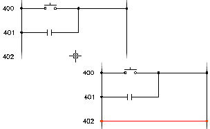
Index is the increment number for line reference numbering (default = 1). If you do not want every line reference number to show up then you can use the AutoCAD Erase command to get rid of the extras. Do not erase the top-most line reference number. It is the MLR block of the ladder and carries the intelligence.
Note: It is not necessary to enter a value for the length since it is calculated once the first reference, index, and rung values are set.
- Specify whether to create a one-phase or three-phase ladder. If you select to create a three-phase ladder, the Width and Draw Rungs options are unavailable.
- Specify how to draw the rungs.
No Bus just draws the line reference numbers, while No Rungs just draws the hot and neutral bus with rungs. Add rungs with the AutoCAD Electrical toolset Add Rung command or the Insert Wire tool. Select Yes to include a rung automatically at every reference location (skip = 0) or every other line reference position (skip = 1). You can specify whether to skip rungs; specifying a value of Skip = 4 means that four rungs are skipped for every one that is drawn.
- Click OK.
- Specify the start position of the ladder. Enter a start and end value or pick a point on the drawing.
During ladder insertion, the current wire type displays at the command prompt. You can override it by typing in the hotkey "T" and selecting a new wire type from the Set Wire Type dialog box. The new wire type becomes the current wire type and the command continues with the ladder insertion.
- Specify the last reference number for the ladder. If you entered values in the step above, this step is not necessary.
- Click to insert the ladder.
Note: Use AutoCAD Move to relocate an entire ladder. Make sure you that get the entire ladder including the first line reference number (the MLR block insert). Select the Revise Ladder button and then click Cancel on the dialog box. Using this command forces AutoCAD Electrical toolset to reread and update its internal ladder location list.
Insert Rungs
Adds a ladder rung at the line reference nearest to a point you select inside the ladder.
Both bus wires must be visible on the screen.
- Click . Find
- Select a blank space anywhere between the hot and neutral bus wires to add the rung.
During rung insertion, the current wire type displays at the command prompt. You can override it by typing in the hotkey "T" and selecting a new wire type from the Set/Edit Wire Type dialog box. The new wire type becomes the current wire type and the command continues with the rung insertion.
If the new rung encounters a schematic device floating in space, it tries to break the wire across the device.
Set Ladder Defaults on the WD_M Block
- Open the WD_M drawing found at \Users\Public\Documents\Autodesk\Acade {version}\libs\{library}\WD_M.dwg.
- Change the default values of the attribute definitions.
- DLADW: default ladder width
- RUNGDIST: default ladder rung spacing
- PH3SPACE: default 3-phase spacing
- Save and exit the drawing.
You can permanently change the relative position of line reference numbers and text size by modifying the RUNGFIRST attribute definition.
- Display the drawing of the MLR block. The file names found at \Users\Public\Documents\Autodesk\Acade {version}\libs\{library}\ are:
- WD_MLRH.dwg: for horizontal rung / vertical ladders
- WD_MLRV.dwg: for vertical rung / horizontal ladders
- WD_MLRHX.dwg: hexagon-shaped user block (horizontal rung / vertical ladders)
- WD_MLRVX.dwg: hexagon-shaped user block (vertical rung / horizontal ladders)
- Change the default values as desired, but do not delete any of the attributes you find.
- Move or change the text size of the RUNGFIRST attribute definition.
- Save and exit the drawing.
brownburpecto1977.blogspot.com
Source: https://knowledge.autodesk.com/support/autocad-electrical/learn-explore/caas/CloudHelp/cloudhelp/2019/ENU/AutoCAD-Electrical/files/GUID-4797FDE4-99EF-4E28-AC64-DA58390BA7B6-htm.html
0 Response to "How to Draw a Ladder in Autocad"
Postar um comentário